
The LCC development workflow for Quest 3 is slightly different from Meta's official VR project creation workflow: Meta's official modifications to the Unity configuration will cause LCC rendering to be incompatible with the recommended workflow in their development documentation. See Meta's official workflow at Set up Unity for XR development. Building on that workflow, this guide explains how to integrate the LCC Unity SDK to render 3DGS scenes.
Version Requirements
The software and plugin versions used in this guide are as follows. It is recommended to develop with the same versions; other untested versions may have compatibility issues:
| Software / Plugin | Version |
|---|---|
| Unity | v6000.0.69f1 |
| Meta XR All-in-One SDK | v205.0.0 |
| LCC Unity SDK | v2.1.35 and above |
Note:
- The Meta SDK only supports URP's Linear color space, and LCC scenes rendered in this color space will appear slightly washed out.
- The Unity version, the Meta SDK version, and the LCC SDK version all affect rendering and performance, so try to keep each software version consistent with this guide.
Development Workflow
Step 1: Create a URP project
Select Universal 3D in the project template, as shown below:
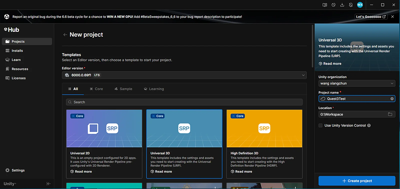
Create a Universal 3D (URP) project
Step 2: Switch the platform
After the project is created, select File → Build Profiles from the Unity menu to open the build window, and switch the platform to Android, as shown below:
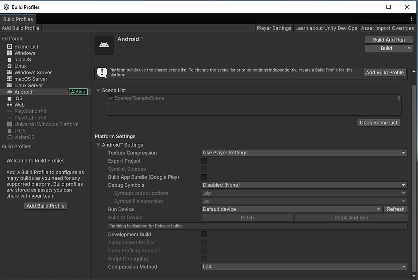
Switch the platform to Android in Build Profiles
Step 3: Import Unity OpenXR
Open the UPM window via the Unity menu Window → Package Manager, select Unity Registry in the left list, enter OpenXR in the search box, select OpenXR Plugin from the search results and install it, as shown below:
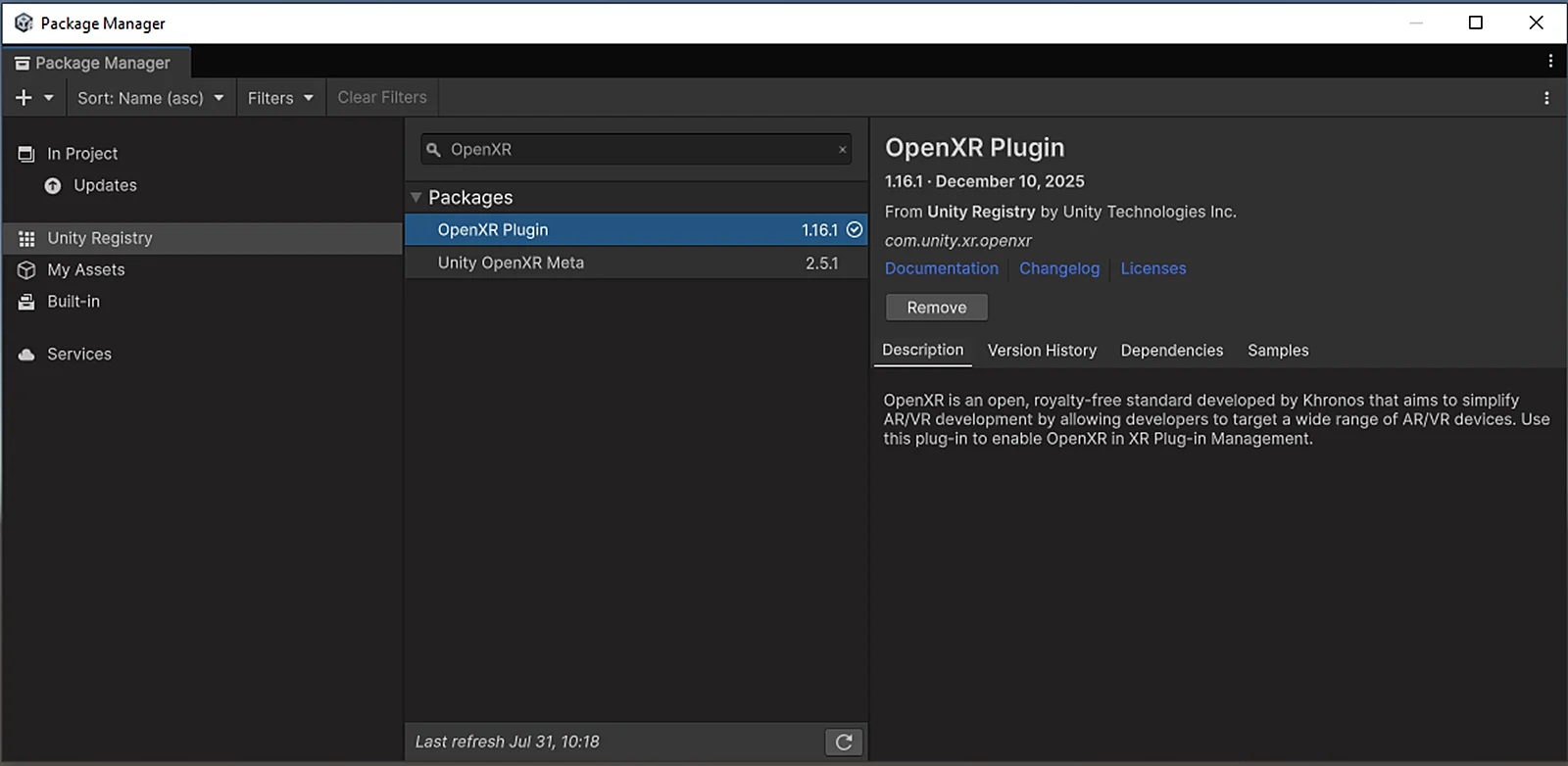
Install the OpenXR Plugin from Unity Registry
Step 4: Import XR Interaction Toolkit
Select Unity Registry in the left list, enter XR in the search box, select XR Interaction Toolkit from the search results and install it, as shown below:
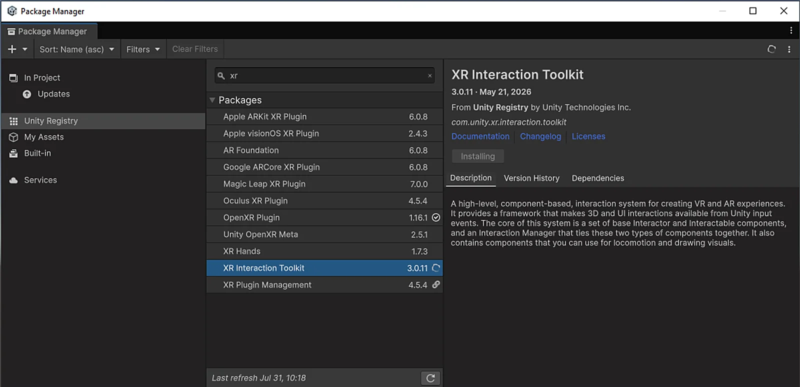
Install XR Interaction Toolkit from Unity Registry
Step 5: Import Meta XR All-in-One SDK
The Meta XR All-in-One SDK is Meta's XR development toolkit; see Meta XR All-in-One SDK (UPM).
Before using this SDK, add it to your personal assets in the Unity Asset Store: https://assetstore.unity.com/packages/tools/integration/meta-xr-all-in-one-sdk-269657. Then open UPM via Window → Package Manager, select My Assets on the left, enter Meta XR in the search box, and install Meta XR All-in-One SDK, as shown below:
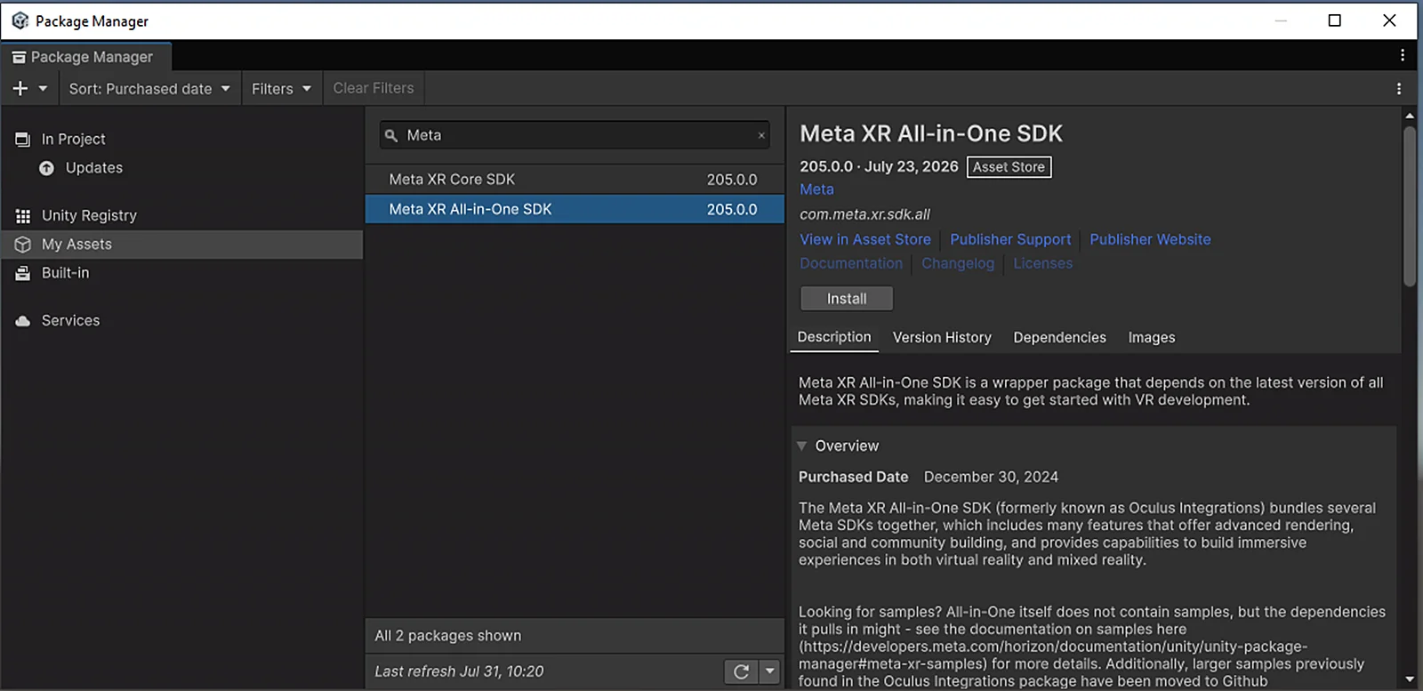
Install Meta XR All-in-One SDK from My Assets
Step 6: Import the LCC Unity SDK
Open the UPM window via the Unity menu Window → Package Manager, click + on the left, select Install package from disk from the drop-down menu, locate the LCC Unity SDK, and select the package.json file to import it, as shown below:
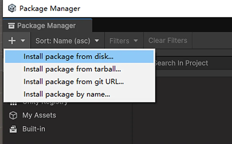
Import the LCC Unity SDK via Install package from disk
After completing the steps above, restart Unity before proceeding with the subsequent settings.
Step 7: Set up the Unity environment
Configure XR Plug-in Management
Select File → Project Settings from the Unity menu bar, select XR Plug-in Management on the left, and check Initialize XR on Startup under both the Desktop and Android platforms, as shown below:
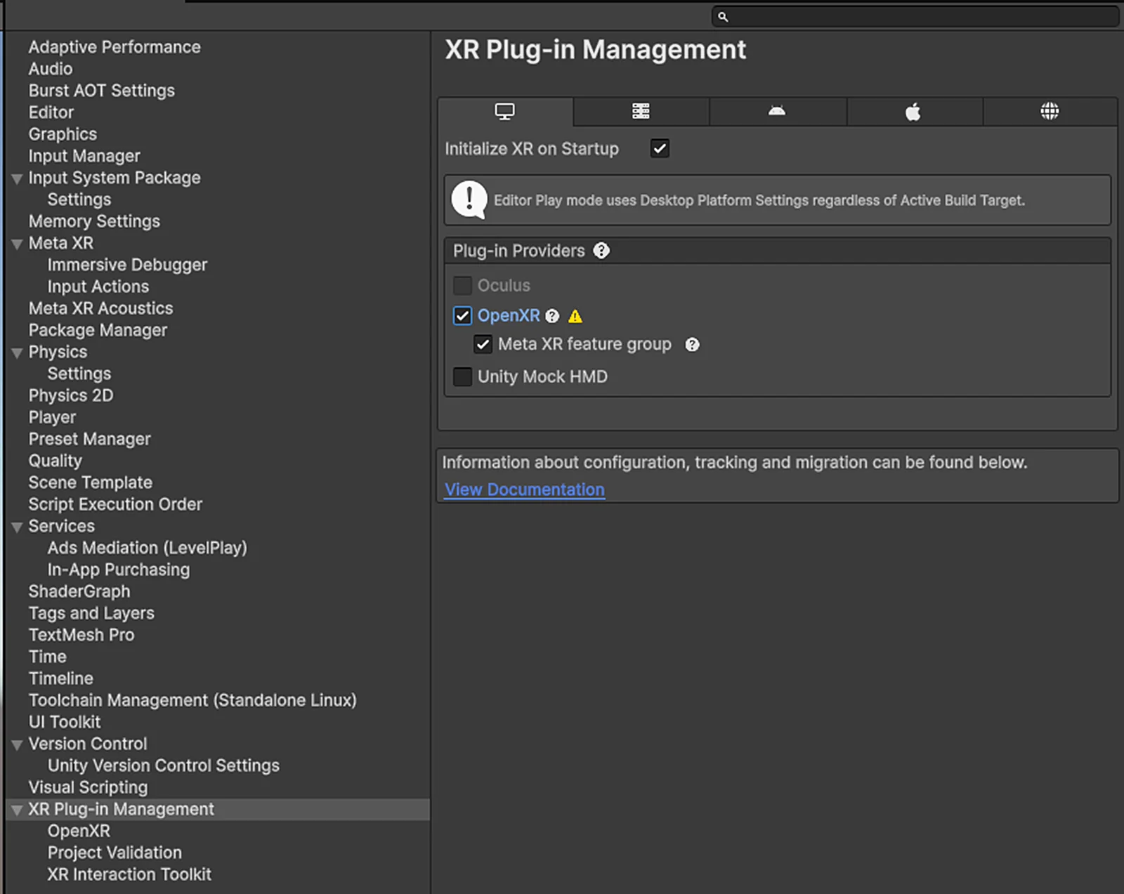
Check Initialize XR on Startup on the Desktop platform
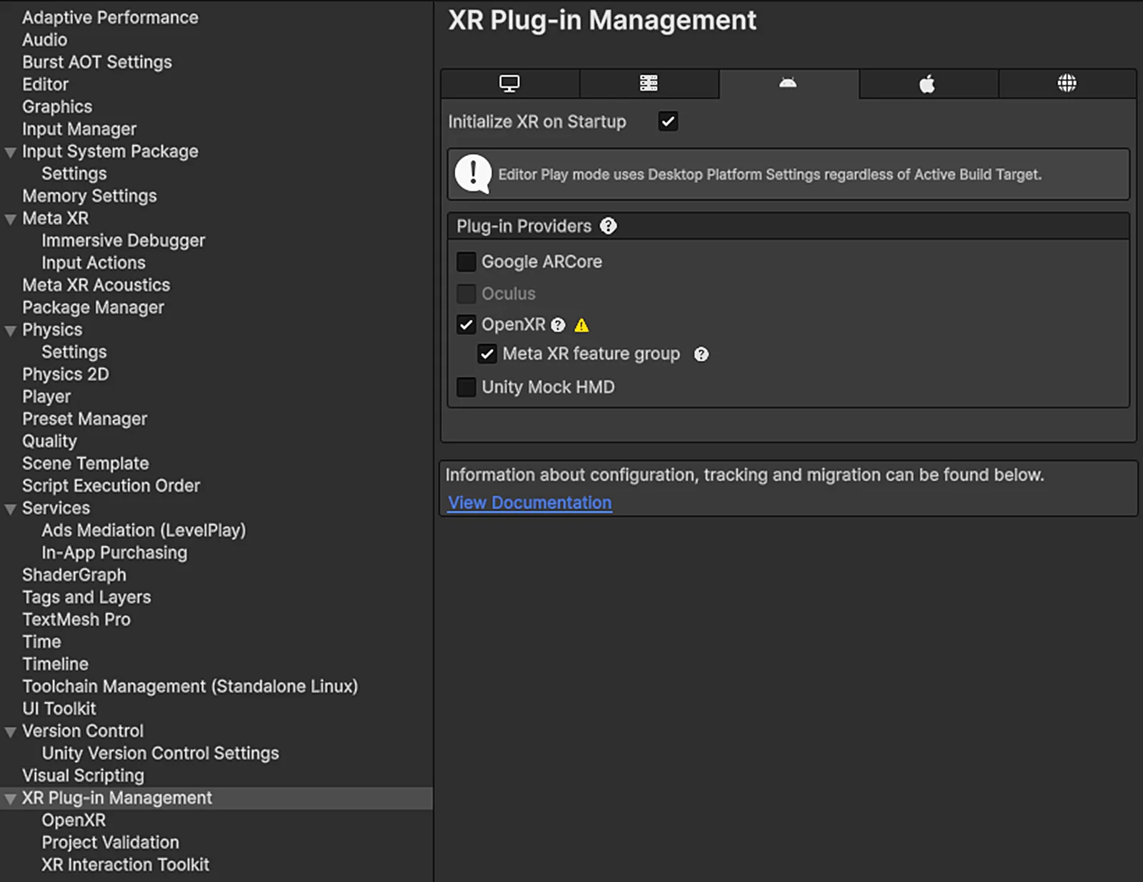
Check Initialize XR on Startup on the Android platform
Select the OpenXR item under XR Plug-in Management, and set the Render Mode for both the Desktop and Android platforms to Multi-pass, as shown below:
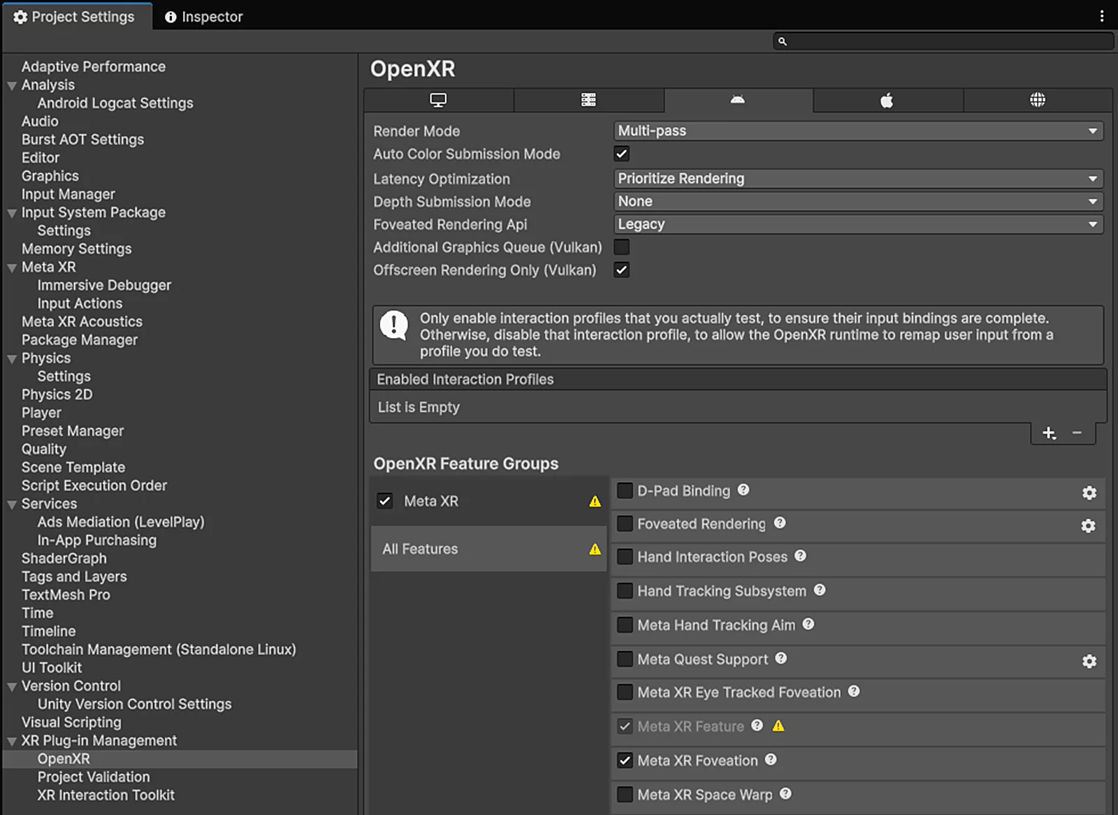
Set the OpenXR Render Mode to Multi-pass
Note: The Meta XR All-in-One SDK will modify the Render Mode value; make sure this value is Multi-pass before building.
Configure Player (Desktop platform)
Select Player on the left of Project Settings, switch to the Desktop platform, expand the Other Settings section, uncheck Auto Graphics API, set Graphics APIs to Vulkan, Direct3D12, Direct3D11, and remove the other graphics APIs; set Color Space to Linear, as shown below:
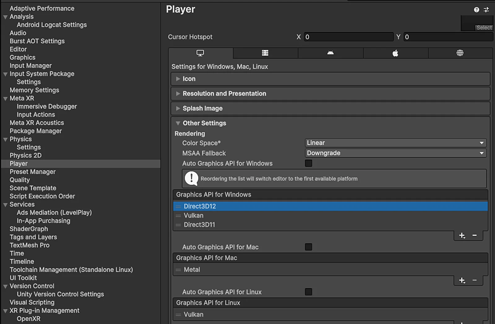
Set the graphics APIs and the Linear color space on the Desktop platform
Configure Player (Android platform)
Select Player on the left of Project Settings, switch to the Android platform, expand the Other Settings section, uncheck Auto Graphics API, set Graphics APIs to Vulkan, and remove the other graphics APIs; set Color Space to Linear (the Meta SDK only supports the Linear color space), as shown below:
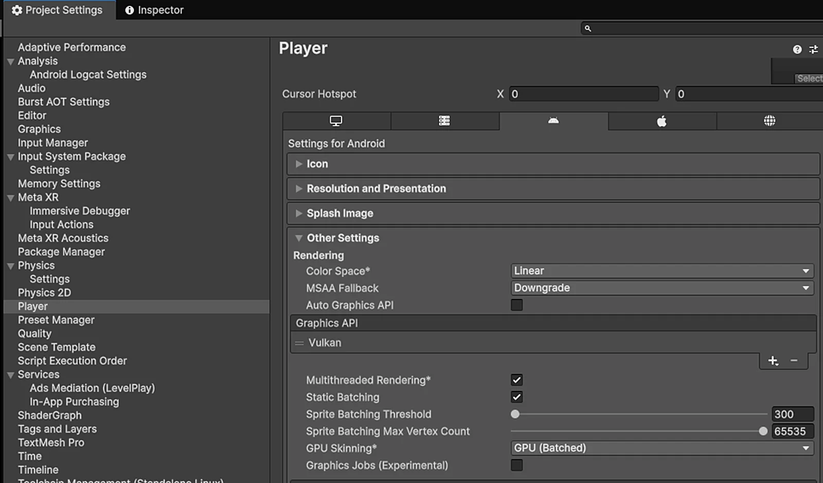
Set the graphics API to Vulkan and the Linear color space on the Android platform
Set Company Name and Product Name
In the Player tab, set Company Name and Product Name correctly, as shown below:
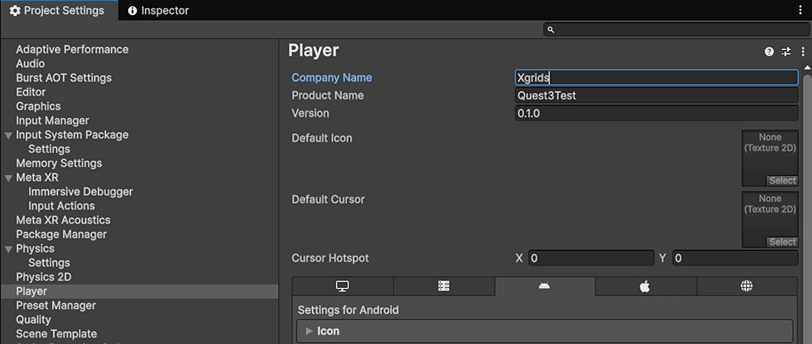
Set Company Name and Product Name
Set the Android platform scripting backend and input
Scroll down in the Other Settings tab of the Android platform, and set Minimum API Level = Android 12L (API Level 32) or above, Scripting Backend = IL2CPP, Target Architectures = ARM64, Active Input Handling = Input System Package (New), as shown below:
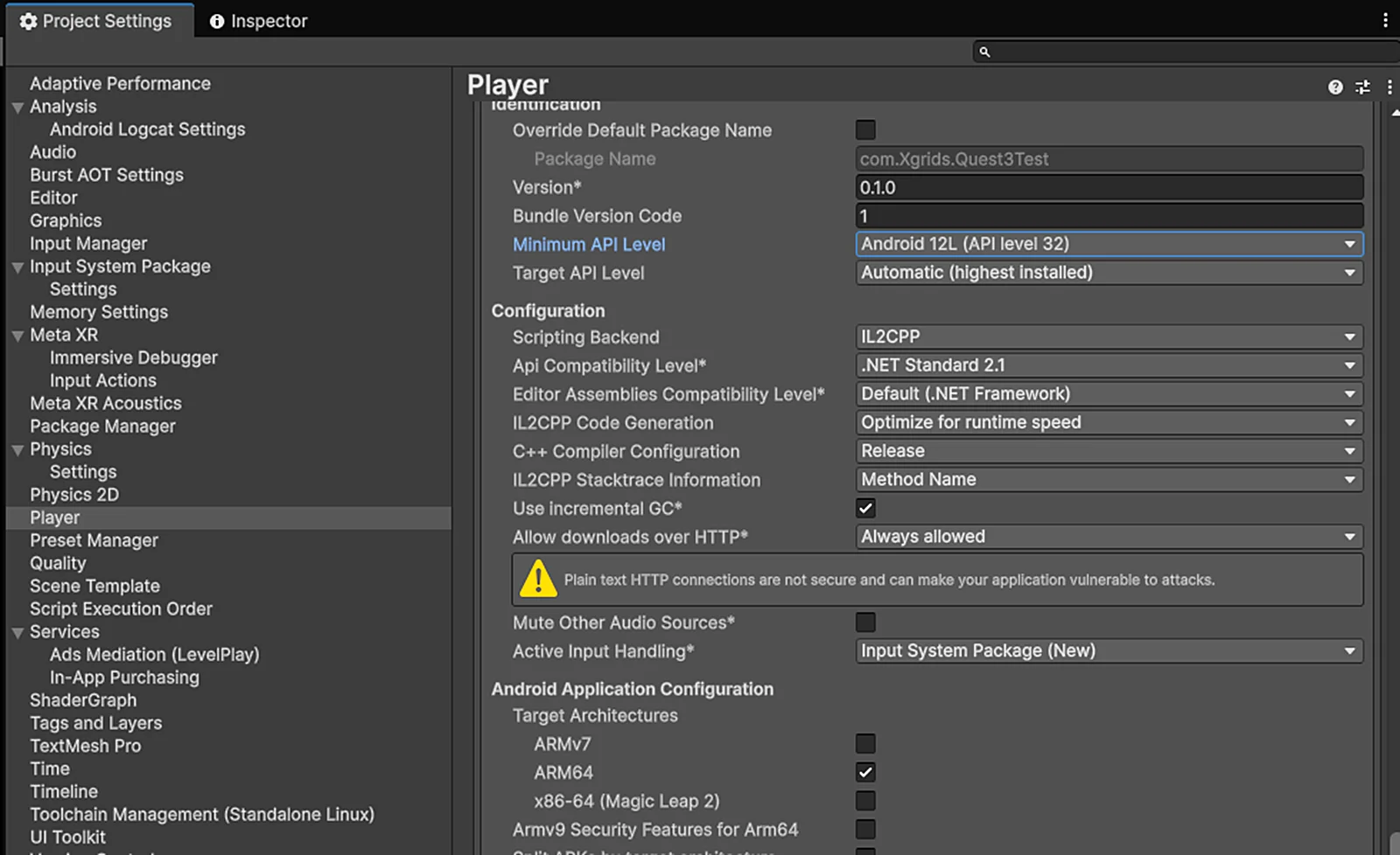
Set Minimum API Level, Scripting Backend, Target Architectures, and Active Input Handling
Check Graphics and Quality
Select Graphics on the left of Project Settings, and check the Render Asset corresponding to the Default Render Pipeline used by the Mobile platform, Mobile_RPAsset in this example, as shown below:
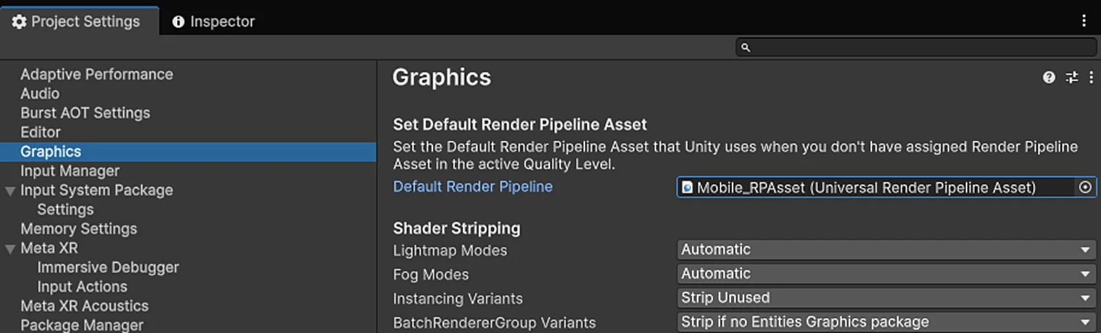
Check the Default Render Pipeline Render Asset on the Mobile platform
Select Quality on the left of Project Settings, check the Render Asset corresponding to the Default Render Pipeline used by the Mobile platform (Mobile_RPAsset in this example), set Resolution Scaling Fixed DPI Factor = 0.7, VSync Count = Don't Sync, as shown below:
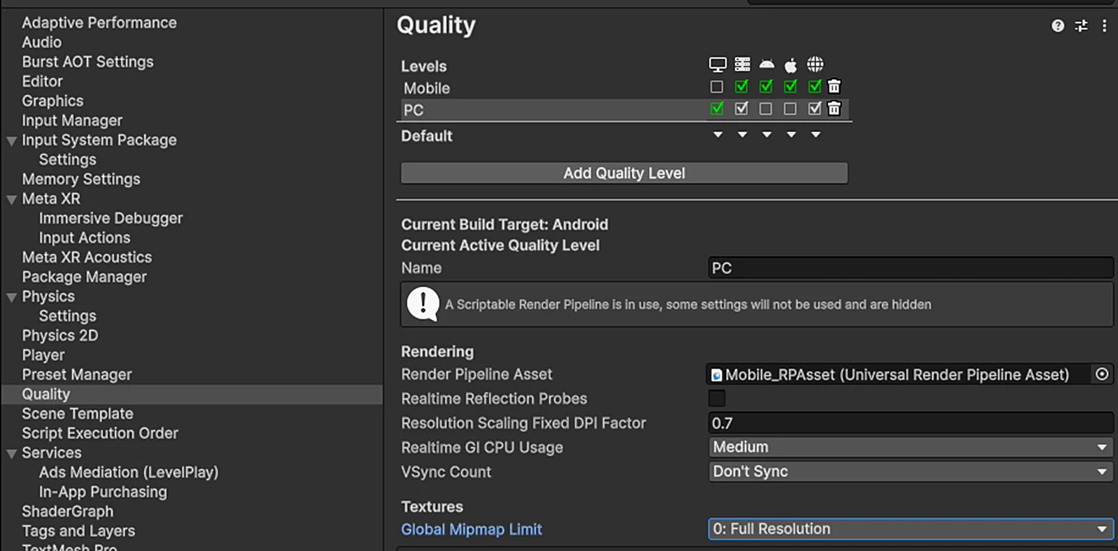
Set the DPI Factor and VSync in Quality
Configure the Render Asset
Find the Render Asset corresponding to the Default Render Pipeline used by the Mobile platform (Mobile_RPAsset in this example). After clicking it, the Asset will be located in the project window (Project). Select the Asset, then in the property window (Inspector): uncheck Depth Texture, Opaque Texture, HDR; set Anti Aliasing (MSAA) = Disabled, Render Scale = 0.7, Upscaling Filter = Automatic, as shown below:
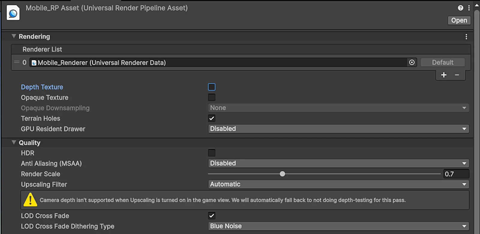
Turn off Depth/Opaque Texture, HDR, MSAA, and set Render Scale = 0.7 in the Render Asset
Find the matching Renderer for this Render Asset, Mobile_Renderer (Universal Renderer Data) in this example, and set its relevant properties in the property window (Inspector), as shown below:
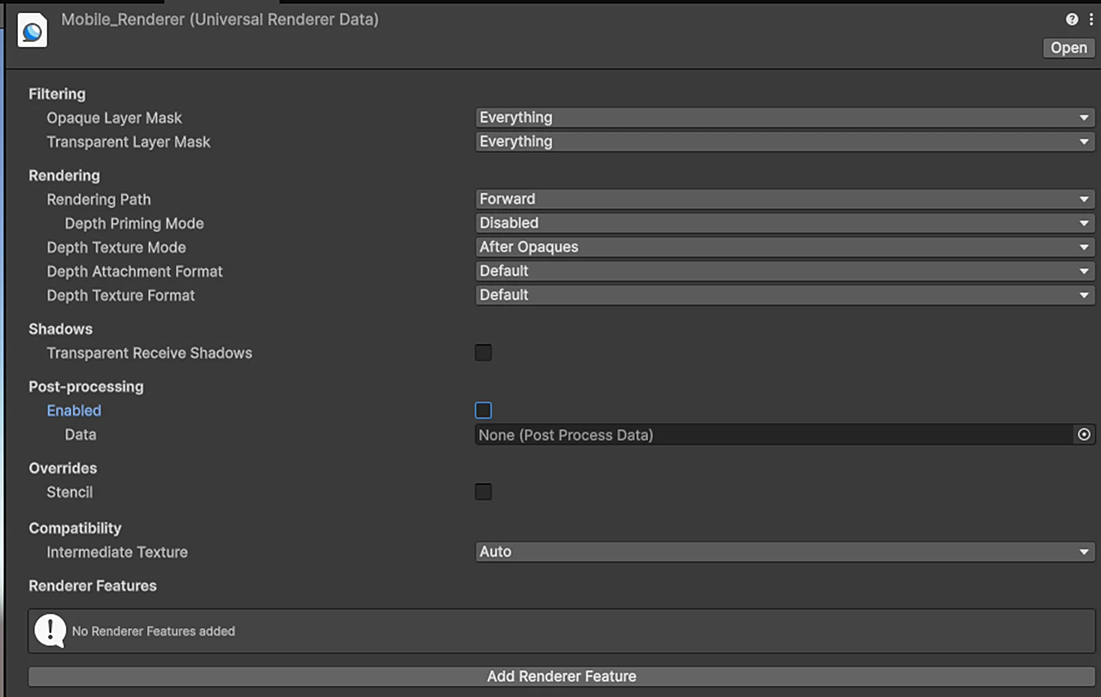
Configure the Mobile_Renderer (Universal Renderer Data) properties
Project Validation
Select XR Plug-in Management on the left of Project Settings, then select Project Validation. Fix the red-marked validation items — click the Fix button on the right of each red item to fix it; the yellow warning items can be fixed as needed or left unhandled for now. Before processing, as shown below:
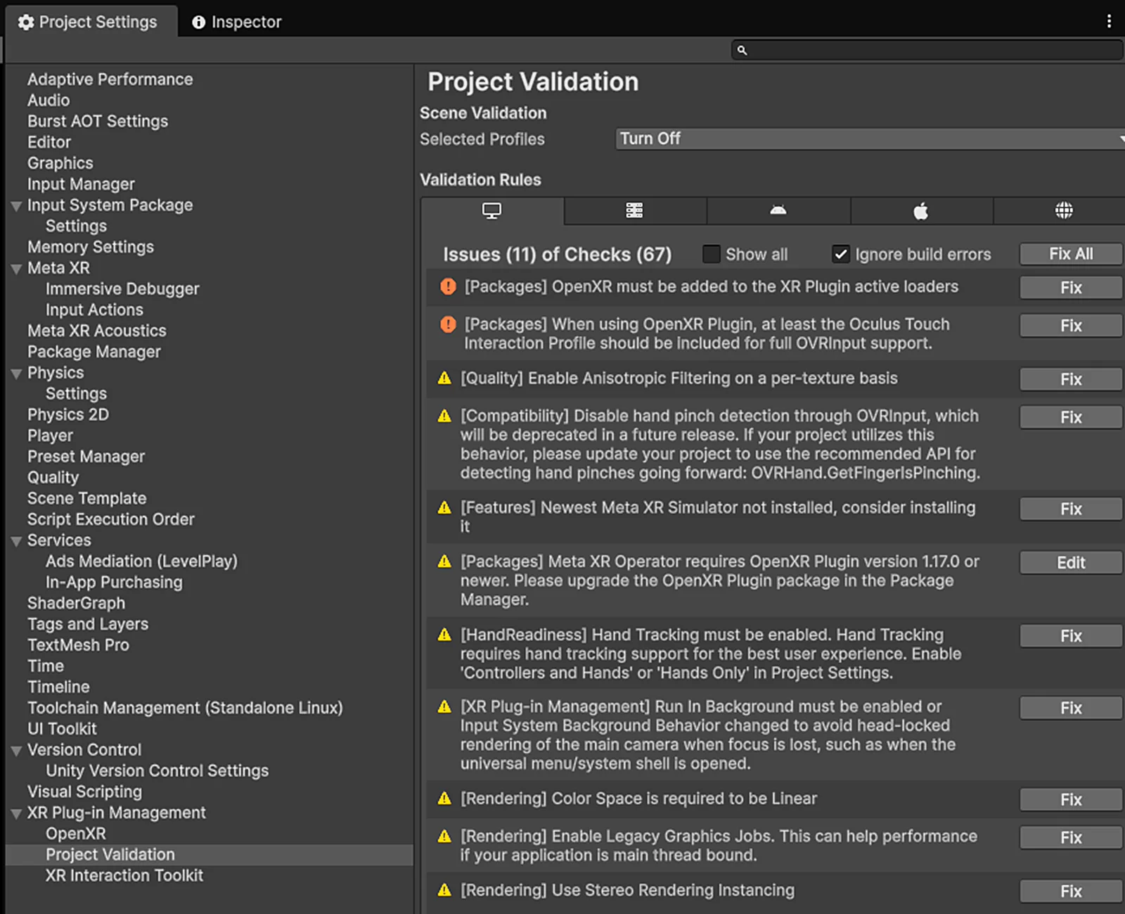
Project Validation before processing (red-marked items present)
After processing, as shown below:
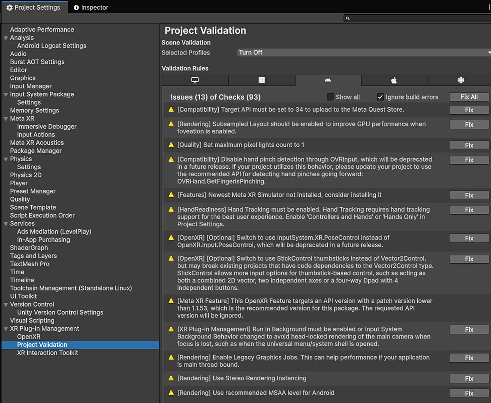
Project Validation after processing (red-marked items fixed)
Step 8: Create the scene
This example starts from a brand-new scene (Scene). After creating a Unity scene, delete the Main Camera GameObject in the hierarchy window (Hierarchy), then right-click in an empty area of the window and select XR → XR Origin (VR) from the popup menu, as shown below:
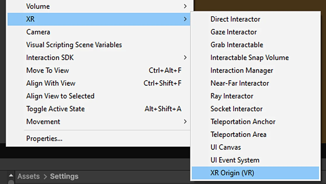
Create XR Origin (VR) via the right-click menu
Step 9: Configure the scene
Select the XR Origin (VR) GameObject in the hierarchy window (Hierarchy), and in the XR Origin component of the property window (Inspector), set Tracking Origin Mode to Floor, as shown below:
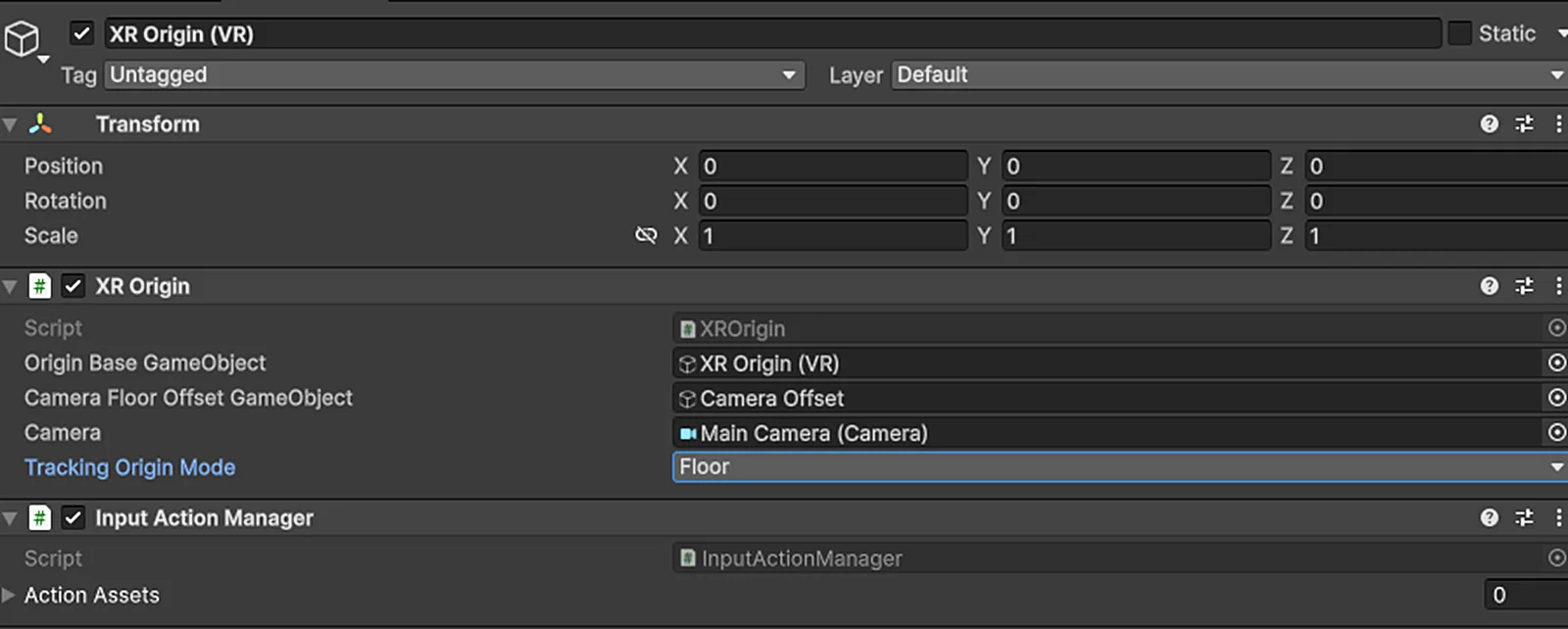
Set the XR Origin Tracking Origin Mode to Floor
Select the Main Camera GameObject under XR Origin (VR) in the hierarchy window (Hierarchy), and set the Camera properties in the property window (Inspector):
| Property | Recommended value | Description |
|---|---|---|
| Field of View | 60 | FOV |
| Clipping Planes → Near | 0.2 ~ 0.3 | Near clipping plane |
| Clipping Planes → Far | 3000 ~ 5000 | Far clipping plane, covering large-scale scenes |
| Anti-aliasing | No Anti-aliasing | Anti-aliasing disabled by default |
| Opaque Texture | Off | Off by default |
| Depth Texture | Off | Off by default |
| Background Type | Solid Color | A solid color is recommended |
| Background | Black | The default background color is recommended to be black |
| HDR Rendering | Off | Off by default |
| MSAA | Off | Off by default |
| URP Dynamic Resolution | Off | Off by default |
Other properties are as shown below:
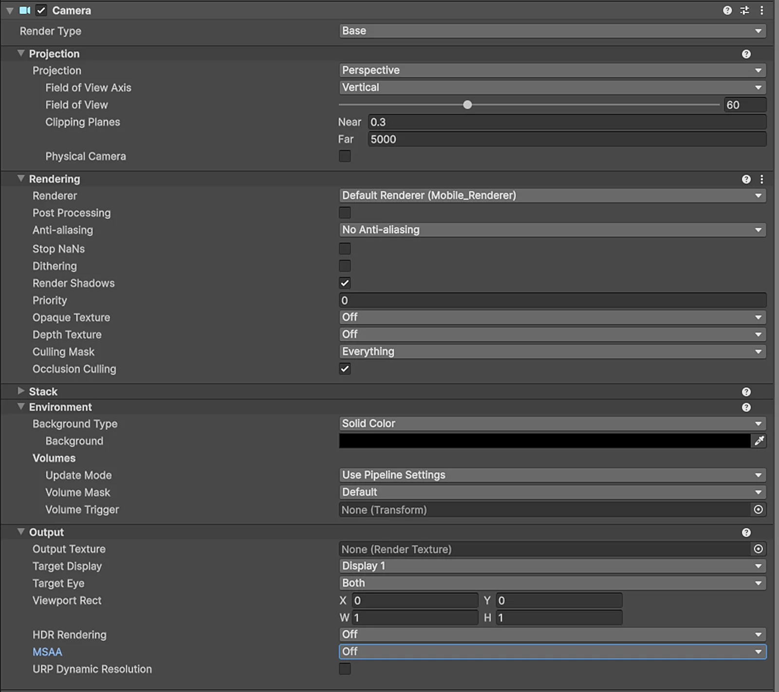
Set the Camera component properties of Main Camera under XR Origin (VR)
Step 10: Write code to load the scene
Right-click Create Empty in the hierarchy window (Hierarchy) to create an empty object, name it LCCManager, normalize its Transform, and attach the LCCManager script to it, as shown below:
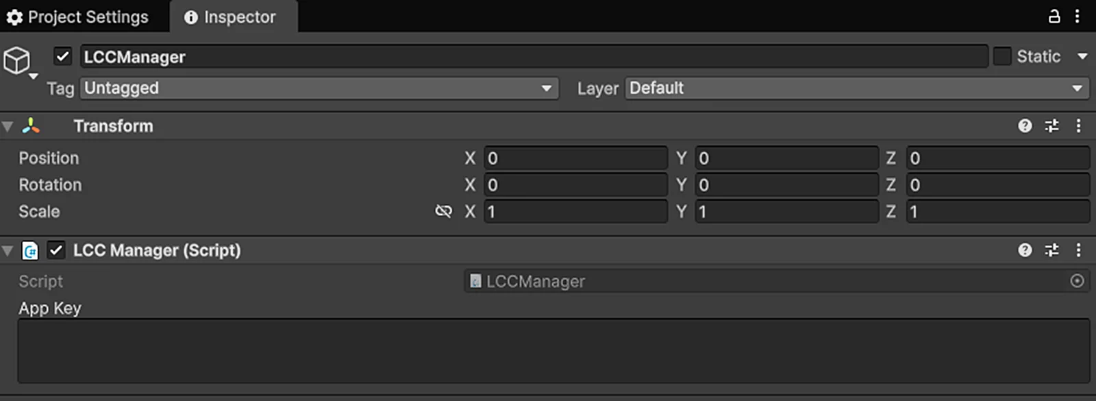
Create an LCCManager empty object and attach the LCCManager script
Right-click Create Empty in the hierarchy window (Hierarchy) to create another empty object, name it LCCRenderer, and set its Transform Rotation.x = -90, Scale.x = -1, as shown below:
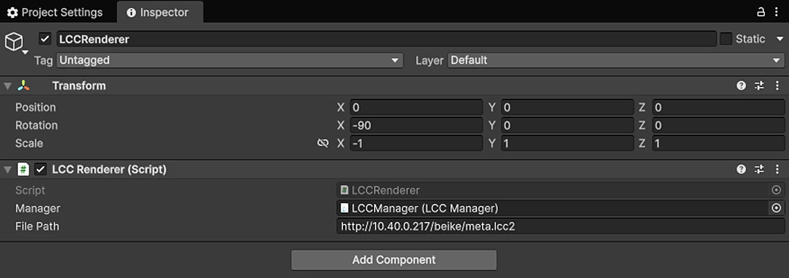
Create an LCCRenderer empty object, and set Rotation.x = -90 and Scale.x = -1 to align the coordinate systems
Rotation.x = -90 and Scale.x = -1 are the alignment transformation from the LCC data coordinate system (Z-up, right-handed) to the Unity coordinate system (Y-up, left-handed); see "LCC data coordinate system" in Unity SDK Introduction.
Write a C# script named LCCRenderer.cs with the following code:
using LCCCore;
using UnityEngine;

public class LCCRenderer : MonoBehaviour
{
    public LCCManager m_manager;
    public string m_FilePath;

    private LCCCore.Renderer m_renderer;

    void Start()
    {
#if UNITY_EDITOR
        m_manager.SetPlatformType(PlatformType.PC);
        m_renderer = m_manager.GetRender(this.gameObject.transform);
        m_renderer.Load(m_FilePath, onProgress, onLoaded);
#else
        m_manager.SetPlatformType(PlatformType.Quest);
        m_renderer = m_manager.GetRender(this.gameObject.transform);
        m_renderer.Load(m_FilePath, onProgress, onLoaded);
        //m_renderer.Load($"{Application.persistentDataPath}/LccData/meta.lcc2", onProgress, onLoaded);
#endif
    }

    private void onProgress(float v)
    {
        Debug.Log("progress:" + v);
    }

    private void onLoaded()
    {
        m_manager.SetStartLod(2);
        m_renderer.SetEnvironment(false);
        Debug.Log("Data loaded");
    }
}
Attach the script to the LCCRenderer GameObject in the hierarchy window (Hierarchy), then drag the LCCManager GameObject to the script's Manager property in the property window (Inspector), and finally fill in the LCC file path, then build and run.
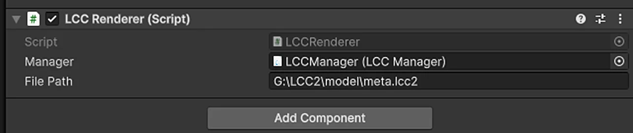
Attach the LCCRenderer script to the object, and bind the Manager and the file path
To make it easy to debug in the Unity Editor and build directly to an Android device, the code uses compile macros to distinguish the runtime environment: use the PC platform in the Unity Editor, and use the Quest platform on a Quest device.
For Quest devices, it is recommended to place the data source on a server; during testing you can also use the data source directly on the device. The specific steps are:
- Run the built app on the Quest device once.
- After the app is installed, enter its data directory (generally Quest device storage → Android → data → app BundleID → Files; refer to the Android app installation path for the specific directory), and create an
LccDatafolder under the Files subdirectory. - Copy all LCC data sources into the
LccDatafolder.
Note:
- In practice, it is recommended to place the Quest app's data source on a server rather than packaging it directly into the app.
- The Quest 3 device's on-screen rendering capability for 3DGS is about 700,000 Gaussian primitives, roughly two orders of magnitude lower than the PC-side capability of about 25 million. It is recommended mainly for rendering and displaying small scenes and single objects; large scenes will be smoother with PC streaming.
- When rendering large LCC scenes, it is recommended to set StartLOD to
2and disable the environment data display (as shown in the sample code).
Related Reference
- For project settings and performance optimization, see the Project Settings Optimization Guide and Render Performance Parameters Guide chapters.
- For other Meta development workflows, refer to the official documentation: Meta Developer Documentation.
- During Quest development, set the Desktop platform Render Mode to Multi-pass in Project Settings → OpenXR; otherwise LCC scenes cannot render normally in Unity (including both the Editor and the Runtime).
This chapter is from the official XGRIDS user manual. Official source (opens in a new tab) · Updated: