
This chapter covers the two ways to capture absolute coordinates: using external control points, or using the GNSS module.
Using External Control Points
Capture control points with the device to transform point cloud coordinates and improve accuracy.
Field Scanning
1. Site visit and planning
If a topographic map is available, plan control points on the map and confirm them on site. If not, plan them on site.
Distribute control points evenly, no more than 100 m apart. Coordinate transformation needs at least 3 control points, not in a straight line. Plan the scan route around the control points and site conditions.
2. Start scanning
Turn on the scanner (see Data Capture).
3. Add external control points during scanning
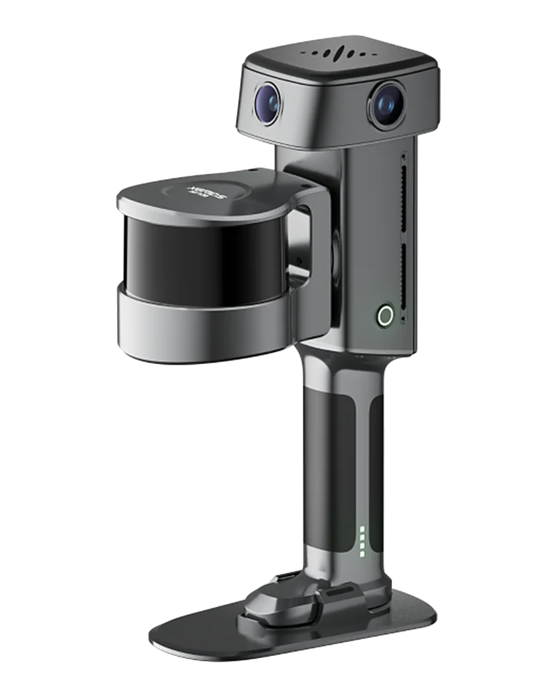
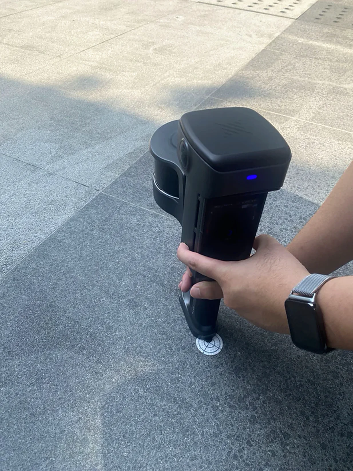
Using the control point marker on the bottom of the scanner
Adding ground control points:
- At each control point, enter its name on the device screen.
- Align the scanner's control point tip with the control point.
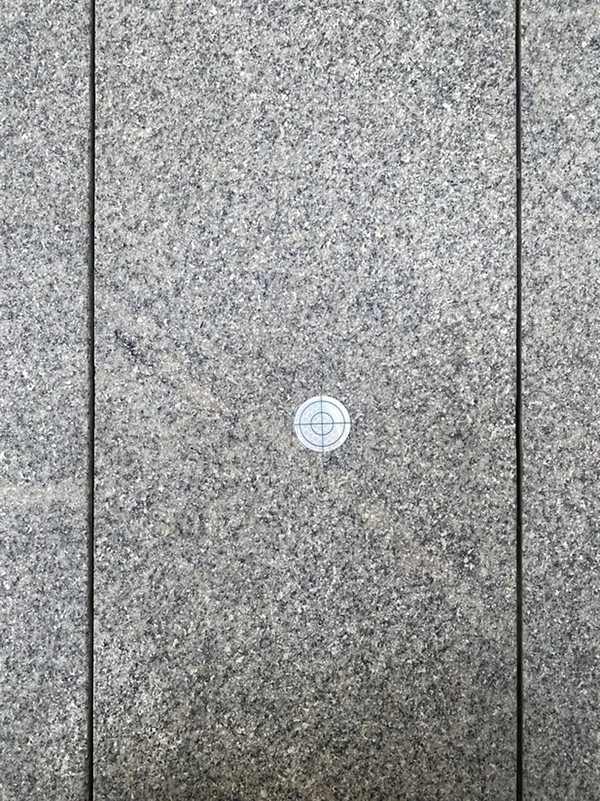
- Add the point by pressing the power button or tapping the screen. Use standard survey nails or target sheets.
- Enter the control point ID and tap OK. The point is captured when the screen shows "Added" or a tone plays.
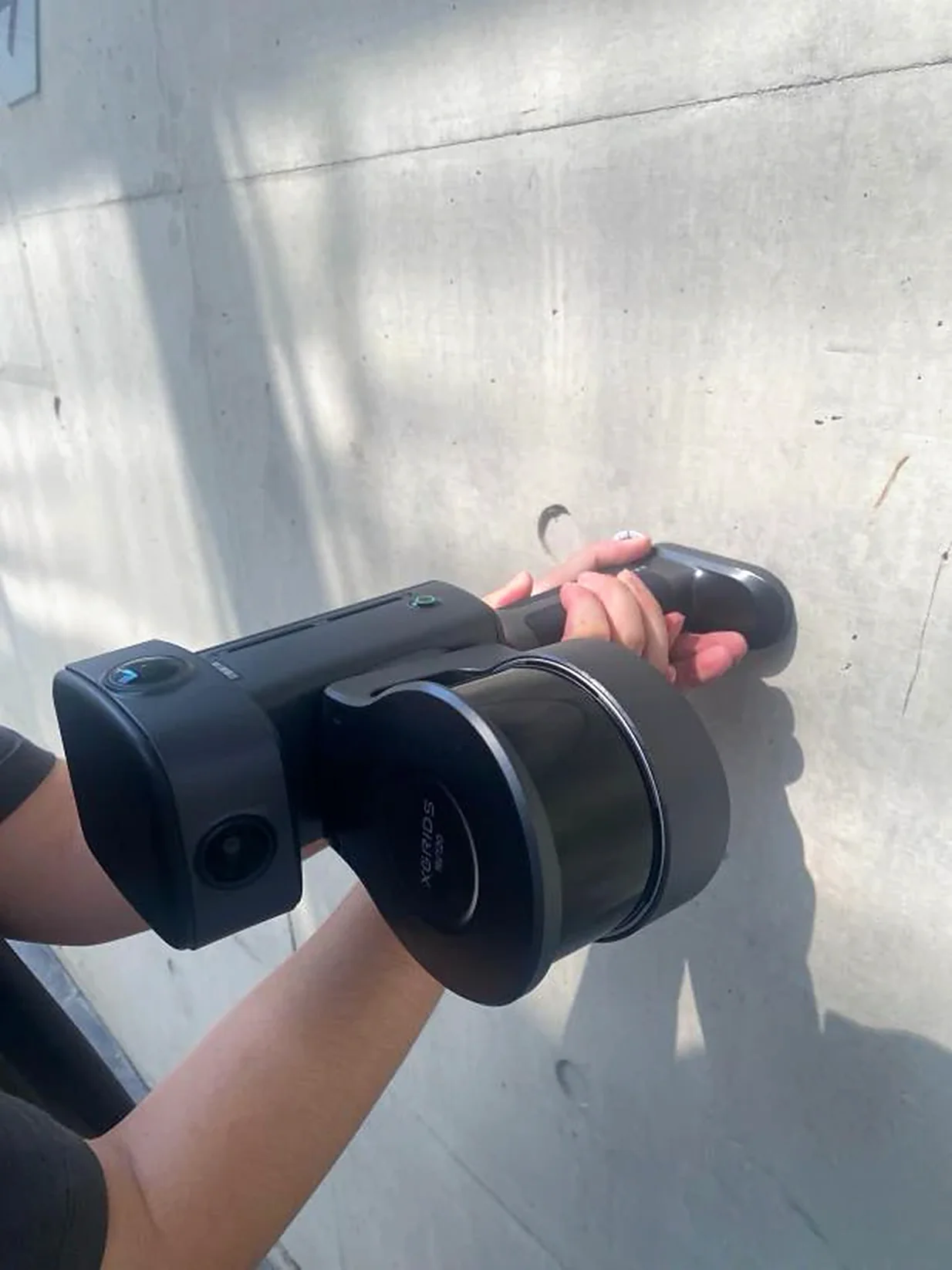
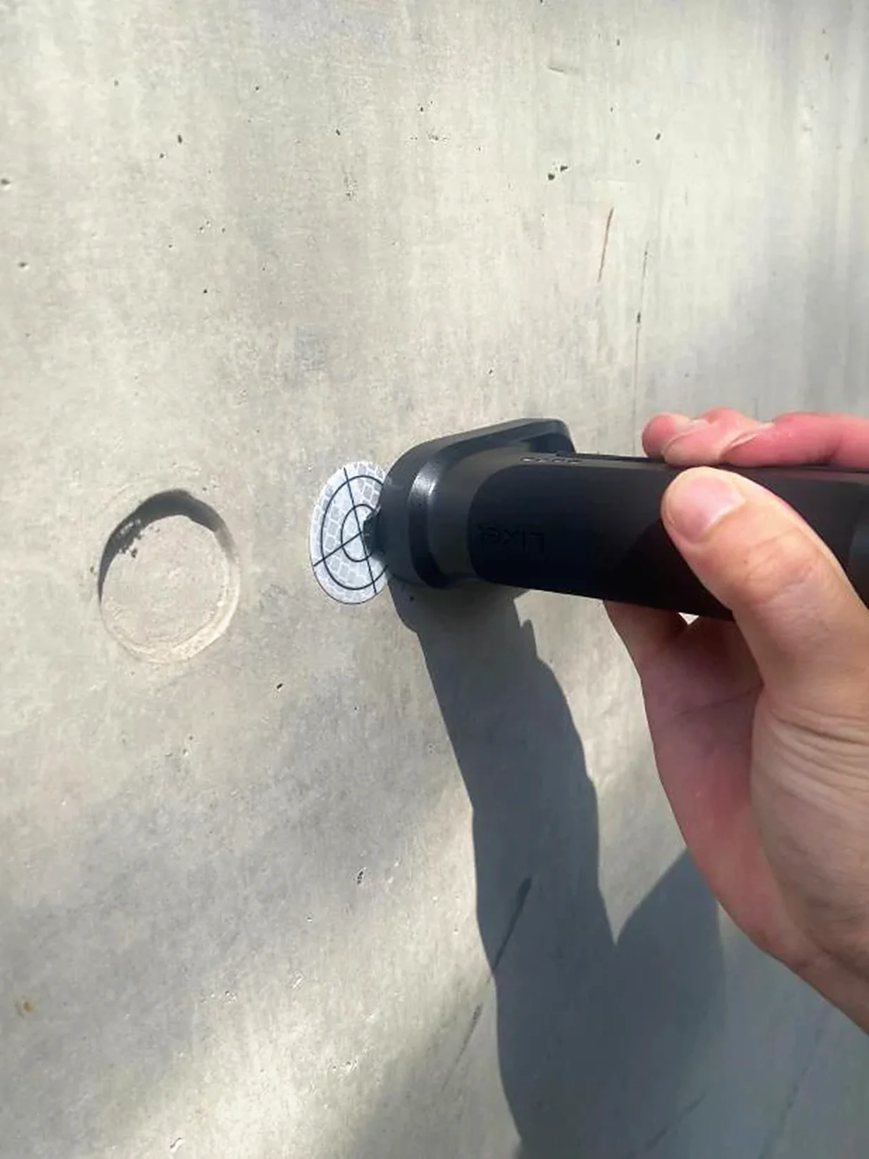
Adding wall control points (supported on the L3):
- At each control point, enter its name on the device screen.
- Keep the LiDAR facing as steady as possible and rotate slowly within the smallest range; fast rotation causes accuracy loss.
- Align the scanner's control point tip with the control point.
- Add the point by pressing the power button or tapping the screen.
- The point is captured when the screen shows "Added" or a tone plays.
- After adding, rotate slowly within the smallest range back to the normal capture posture.
Using a pole
- At each control point, enter its name on the device screen, set Target height to "Pole", and select the correct pole height. Pole height: enter the height shown on the pole.
- Align the pole tip with the control point.
- Add the point by pressing the power button or tapping the screen. Use standard survey nails or target sheets.
- The point is captured when the screen shows "Added" or a tone plays.
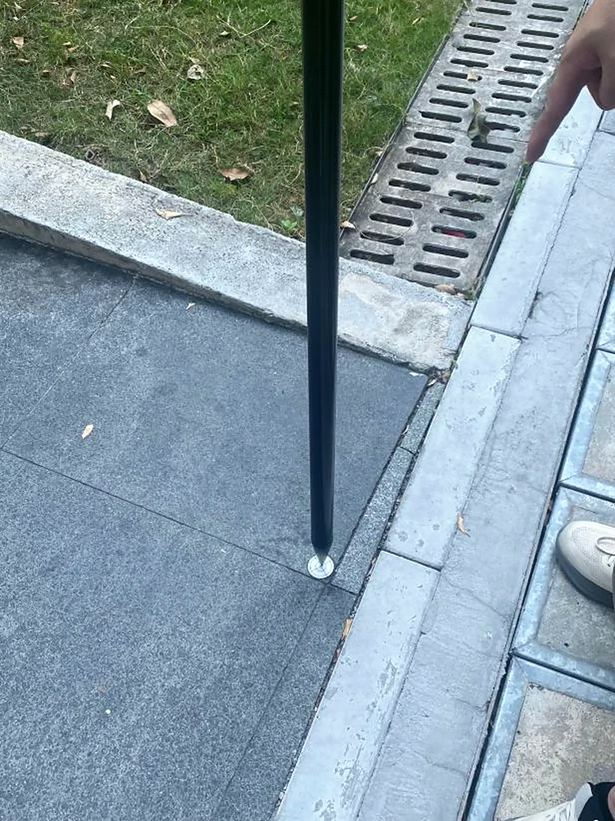
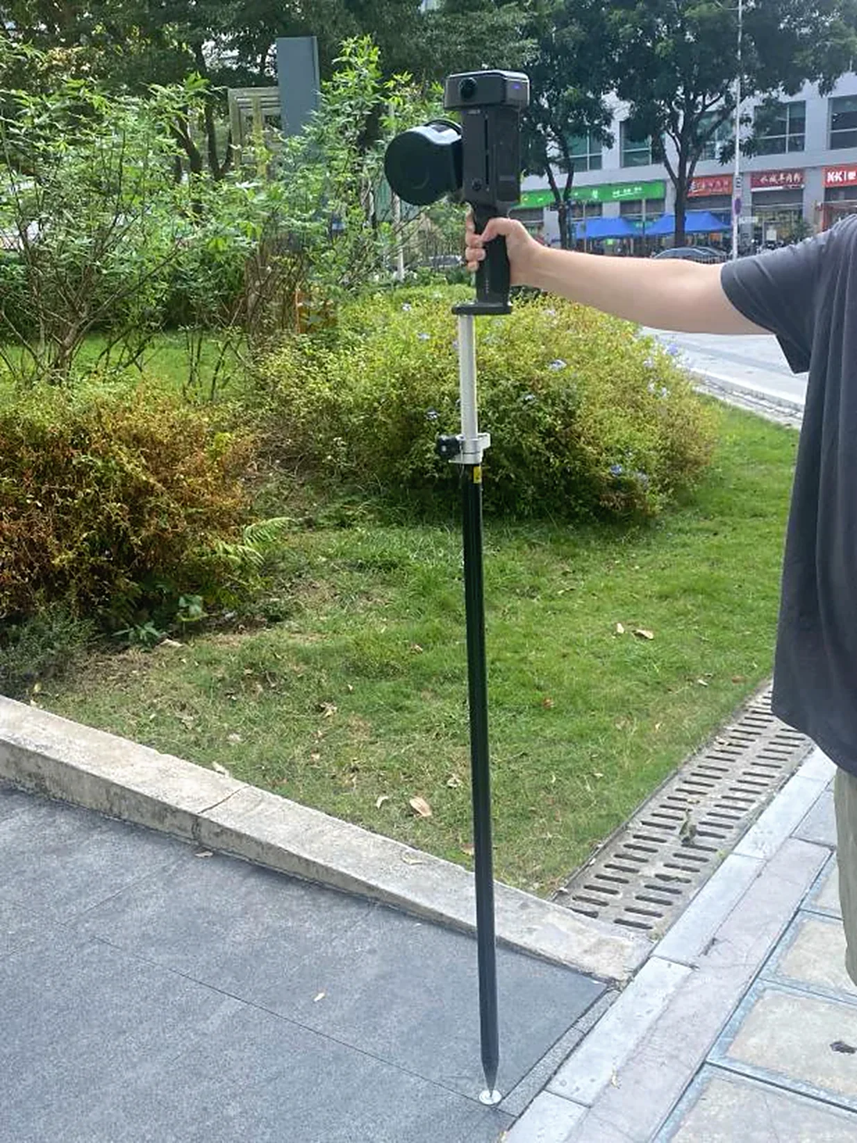
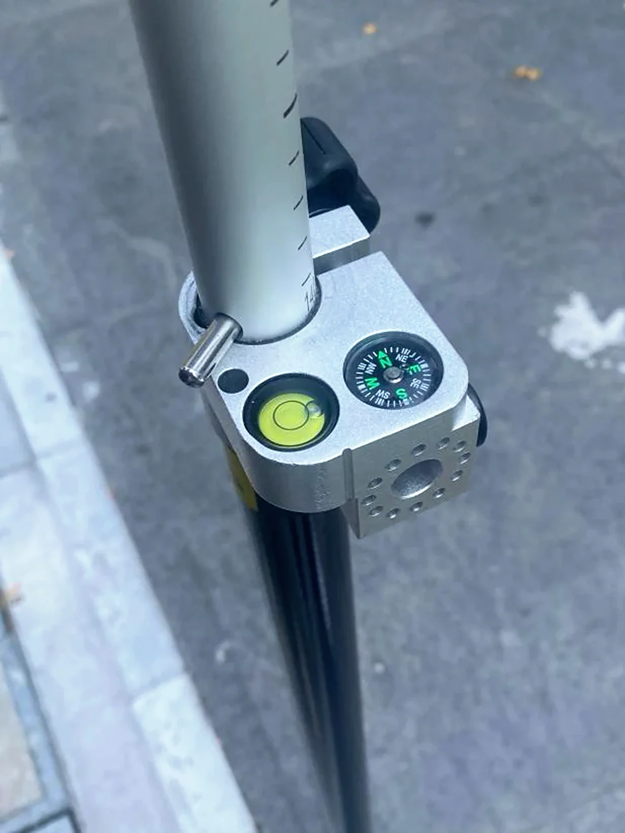
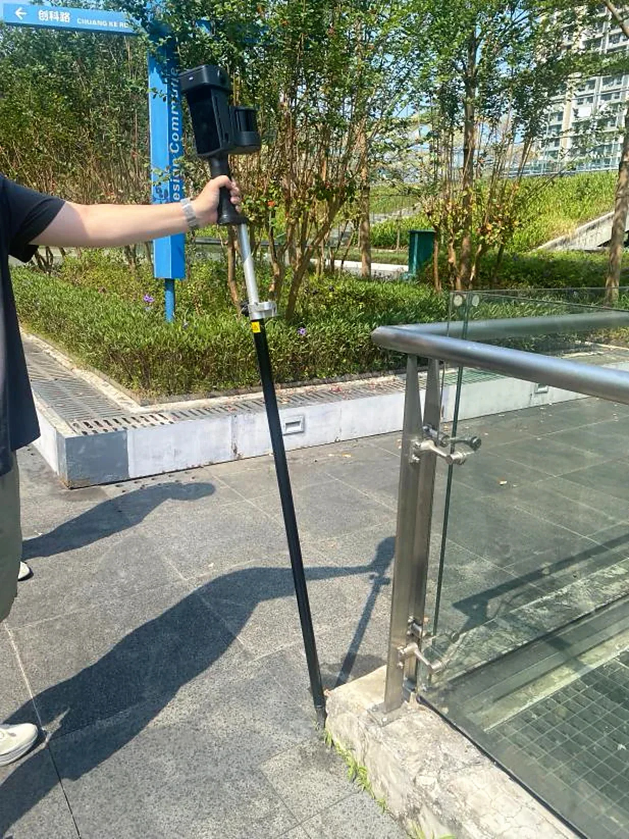
Pole mode usage notes:
- With control points only, the tilt angle may exceed 30°.
- With GNSS, keep the tilt within 15°; exceeding 30° affects the GNSS signal and lowers accuracy.
- While adding, you do not need to center the bubble level; the device compensates for the angle automatically.
- Select the correct pole height. Pole height: enter the height shown on the pole.
4. Stop scanning
Tap the red stop button at the bottom center of the screen. The indicator flashes green rapidly, then turns solid green when the scan ends. Power off or start another scan.
Data Processing
See the LixelStudio user manual.
GNSS Module
RTK or PPK mode records absolute coordinates during capture and improves overall point cloud accuracy.
Field Scanning
1. Scan route planning
Plan a route that keeps GNSS signal strong. For post-processing accuracy, keep any continuous stretch of GNSS loss or unfixed solution under 100 m.
2. Connect the device
Turn on the scanner (see Data Capture).
3. Stop scanning
Tap the red stop button on the right side of the screen. The indicator flashes green rapidly, then turns solid green when the scan ends. Power off or start another scan.
Data Processing
See the LixelStudio user manual.
This chapter is from the official XGRIDS user manual. Official source (opens in a new tab) · Updated: