
Overview
In large-scale 3D reconstruction, multiple large 3DGS models often need to be merged into a single complete scene. XGRIDS provides two technical approaches: capturing data according to fusion requirements before reconstruction, which produces a high-accuracy, seamlessly aligned result; or importing, aligning and merging already reconstructed models in LCC Model Editor. This article covers the applicable scenarios, workflow and technical limitations of each approach.
Choosing an Approach
| Requirement | Recommended Approach |
|---|---|
| A high-accuracy, seamlessly aligned scene for delivery or measurement | Approach A: capture according to fusion requirements before reconstruction |
| Several reconstructed 3DGS models that need to be stitched and merged into a single file | Approach B: import and merge in Model Editor |
| Viewing multiple scenes together, where seam accuracy is not critical | Approach B |
| Higher accuracy required, but the original capture data is unavailable or cannot be recaptured | Approach B (alignment error at the seams must be accepted) |
The essential difference: Approach A performs algorithmic registration during reconstruction and delivers high fusion accuracy, while Approach B aligns and merges manually after reconstruction, which is faster but depends on manual operation.
Approach A: Capture According to Fusion Requirements Before Reconstruction
Recommended for high-accuracy scenarios. Before reconstruction, multiple capture datasets are fed into the software through Map Fusion or Aerial-Ground Fusion, then reconstructed as a single 3DGS model.
Workflow
1. Verify data conditions
- Adjacent datasets must have overlapping capture paths. The overlap must be at least 15 m, and 15~30 m is recommended.
- Choose overlap areas with rich features. Avoid degenerate scenes such as open areas, long corridors and smooth tunnels, which may cause fusion to fail.
- When using RTK, make sure the RTK data of every project is valid and in the same coordinate system.
- When using control points, set at least one control point with the same name in the overlap area of adjacent maps, and make sure control point names are not duplicated across the projects being fused.
2. Select a fusion mode
- Map Fusion: merges multiple point clouds or projects into one map. Suitable for general scenarios.
- Aerial-Ground Fusion: reconstructs drone aerial data together with handheld ground data. The aerial data must cover the handheld scanning area, take-off and landing points must be evenly distributed and photographed, and the landing trajectory must stay above the flight path.
- Large Map Fusion: suitable for merging large areas captured in segments.
3. Software operations
- LCC Studio: go to Process Now and select Map Fusion or Aerial-Ground Fusion. Ground data supports up to 10 datasets (200 min in total).
- LCC Studio Linux v1.6.0 and later: select Map Fusion or Aerial-Ground Fusion in Create Task in the WebUI. Ground data supports up to 20 datasets (500 min in total).
- Ground data requirements for Aerial-Ground Fusion are the same as above. The folder selected for aerial data must contain all drone photos, including both the flight path and the take-off and landing shots: up to 10000 photos in LCC Studio, and up to 15000 in the Linux version.
- Set reconstruction parameters as needed, such as the maximum number of Gaussian points and reconstruction efficiency.
4. Reconstruct as one project
Once fusion validation passes, reconstruct the data as a single project. A successful reconstruction outputs one 3DGS model.
Examples
Map Fusion in LCC Studio
In the following example, the datasets were captured with RTK and the coordinate system is set to WGS84.
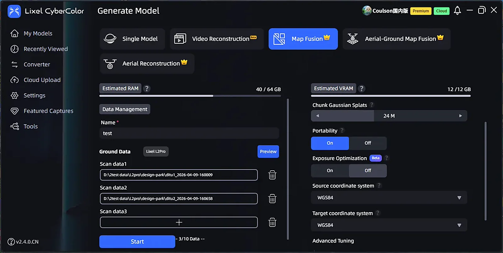
Map Fusion in LCC Studio
Aerial-Ground Fusion in LCC Studio
In the following example, Lixel P1 captured 2 ground datasets along with 4 take-off and landing points and their photos. All aerial data includes RTK and uses the WGS84 coordinate system.
Aerial-Ground Fusion in LCC Studio
WebUI of the Linux version
The operations are similar to those in LCC Studio. The interface language can be switched as needed.
Creating a fusion task in the Linux WebUI
Technical Limitations
- This approach requires the original capture data and does not apply when only reconstructed models are available.
- Data that does not meet the fusion requirements (insufficient overlap, degenerate scenes, non-compliant take-off and landing points or trajectories, invalid RTK, duplicated control point names) will cause fusion to fail or prevent point clouds from aligning.
- Both LCC Studio and the Linux version limit the total duration of ground SLAM data and the total number of drone photos. Exceeding these limits is very likely to cause fusion to fail.
- Only data captured by the same device model is supported. Within the Lixel L series, LiDAR units with different channel counts or ranging capabilities cannot be fused with each other.
- Reconstructing large volumes of data takes a long time and places high demands on RAM, GPU performance, VRAM and disk space. A high-specification workstation or Linux server is required.
Approach B: Import and Merge in Model Editor
Import two reconstructed 3DGS models into LCC Model Editor, align them manually, then merge and export them as a single file.
Workflow
1. Open Model Editor
Click Model Editing in LCC Scene Editor, or launch LCC Model Editor directly.
2. Import the models
- Add Model A and Model B one after another through File → Import.
- Supported import formats: LCC, LCC2, PLY, SOG and SPZ. LCC is automatically upgraded to LCC2, and PLY is converted to LCC2 on import.
- File names must not be duplicated.
3. Align the models
- Use the move, rotate and scale tools in the left toolbar to bring Model B into position against Model A.
- For precise placement, enter translation values (X/Y/Z, step 1), rotation angles (X/Y/Z, 0°~360°) and scale ratios (step 0.01) in the properties panel on the right.
- Use the distance and coordinate measurement tools to check the alignment at the seams.
4. Refine (optional)
- Use the selector and clipping tools to remove redundant overlapping areas.
- Use the color adjustment features to even out color differences between the two models. Brightness, contrast, saturation, highlights, shadows, color temperature, tint and opacity are supported, and global and local adjustments can be combined.
5. Merge and export
- Go to File → Export and select LCC2(SOG), LCC2(SPZ) or PLY.
- Export rules: with no model selected, all models are exported and merged; with multiple models selected, the selection is merged and exported; with a single model selected, only that model is exported.
- The result is a single 3DGS file.
The following three operations serve different purposes and should not be confused:
- Export: exports the merged model as a finished file.
- Returning to LCC Scene Editor and exporting the project: packages the complete project so that other users can continue editing it. The project still contains multiple separate models.
- Publishing the merged scene in LCC Scene Editor: generates a Web Viewer link for online sharing and viewing.
Example
The following shows the basic operations for merging two models. In practice, clipping, color adjustment, cloning and scaling are also required. Saving and exporting regularly during the process is recommended.
Importing, aligning and merging models in Model Editor
Technical Limitations
- Alignment is manual and does not include automatic registration based on overlap areas or control points. The result depends on whether the two models share the same coordinate system (best when both include RTK data or control points with the same name). Otherwise, misalignment, ghosting or discontinuities may appear at the seams.
- This approach does not perform true fusion at the geometry and density level. It places two sets of Gaussian points in the same file, and overlapping areas are not resolved intelligently, which may lead to stacked density or abrupt boundaries.
- Fusion accuracy is not guaranteed. The approach suits presentation and viewing, but not deliverables with strict requirements on seam accuracy or measurement. The absolute coordinates of the source models are not preserved, so merged models have no absolute coordinates.
- Loading two large models and merging them requires considerable VRAM and RAM. When the data volume or clipping workload exceeds the hardware capacity, a save prompt appears. A high-specification workstation is recommended.
Summary
- For seamless, high-accuracy and measurable results, choose Approach A, provided that compliant original capture data is available.
- For fast stitching and a single output file based on finished models, choose Approach B and accept the seam error introduced by manual alignment.
- If the original data is unavailable but higher accuracy is still required, first try to recover the original data so that Approach A can be used. If that is not possible, use Approach B while taking its accuracy limitations into account.
Appendix: Approach Comparison
| Aspect | Approach A (fusion before reconstruction) | Approach B (stitching in Model Editor) |
|---|---|---|
| Input data | Original capture data (multiple datasets) | Reconstructed 3DGS models |
| Alignment | Algorithmic registration (overlap / RTK / control points) | Manual alignment (toolbar and properties panel) |
| Seam accuracy | High, measurable | Depends on manual alignment and coordinate consistency; misalignment is common |
| Nature of fusion | True fusion, reconstructed as one model | Point sets stacked and merged into one file |
| Output | A single 3DGS model | A single 3DGS file (LCC2 / SOG / SPZ / PLY) |
| Main limitations | Requires original data, must meet capture requirements, data volume per reconstruction is capped, same device model only, time-consuming, high RAM and storage demands | No automatic registration, accuracy not guaranteed, overlaps not resolved intelligently, high hardware load |
| Use cases | Delivery, measurement, formal results | Presentation, viewing, quick single-file output |
This chapter is from the official XGRIDS user manual. Official source (opens in a new tab) · Updated: