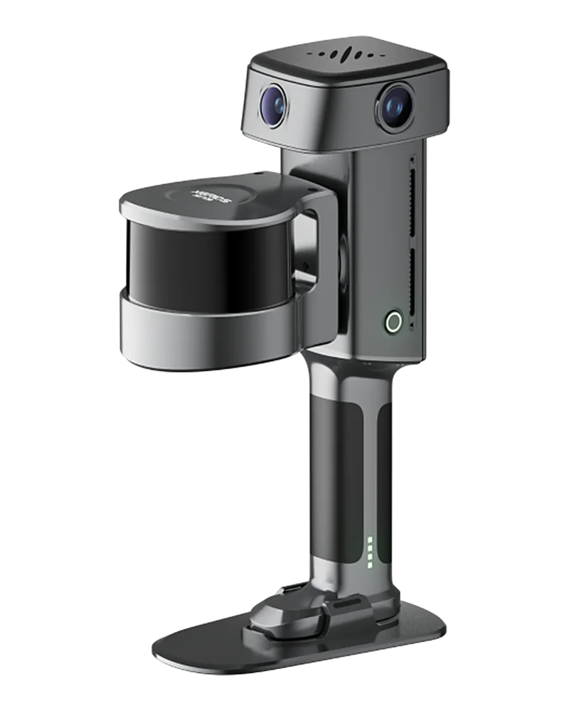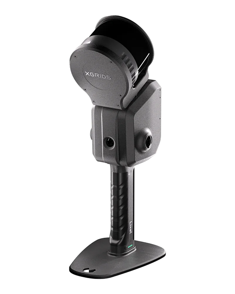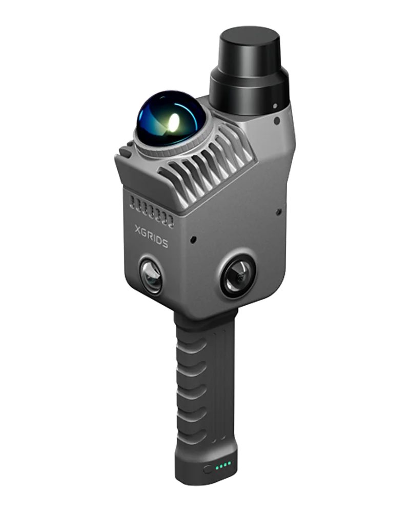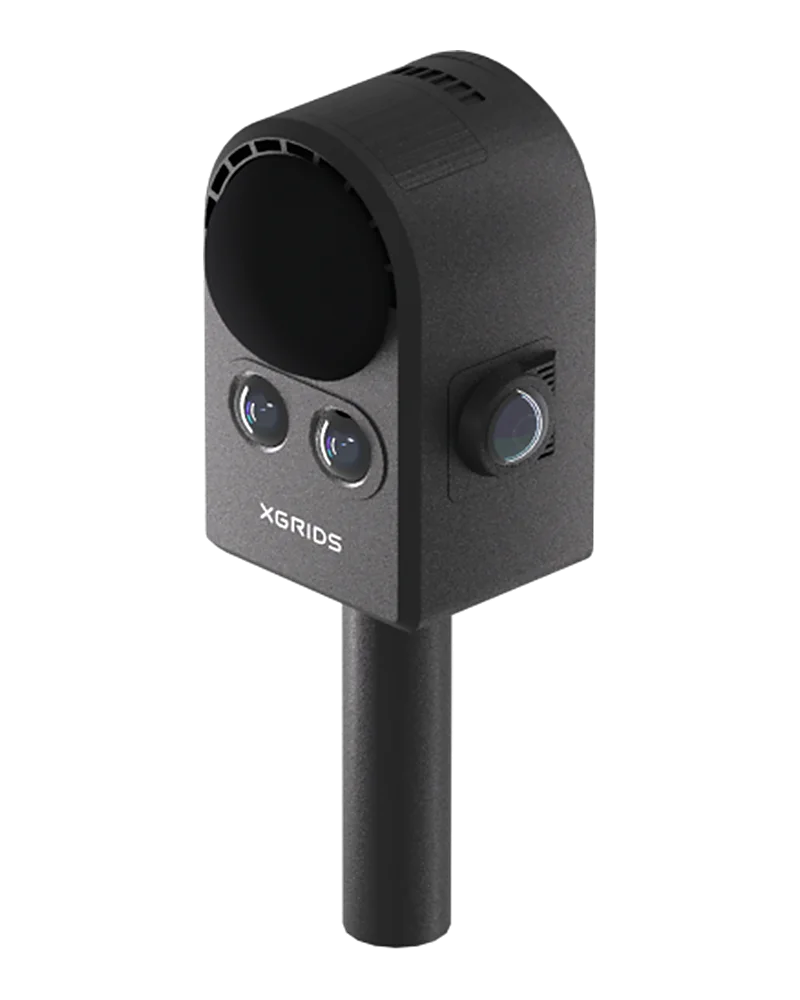

This page describes the full flow of a modeling task from creation to downloading its outputs, the task status transitions, and what the modeling outputs contain. Complete the setup in the Access Guide before calling the APIs.
Input data requirements
Choose the input data based on your modeling needs:
| Input type | Description | Recommendation |
|---|---|---|
| LCC2 scene package | Complete scene directory, including related resources such as info/poses.json, with capture trajectory | Preferred when you need fine model detail, clear textures, and legible text |
| LAS point cloud | LiDAR point cloud without a capture trajectory. Must contain RGB color (Point Data Record Format 2 / 3 / 5 / 7 / 8 / 10). LAS without color is not supported | Preferred when you need high dimensional accuracy |
| PLY point cloud | Complete 3DGS point cloud; can be processed without a capture trajectory | Use when neither an LCC2 scene package nor a LAS point cloud is available |
Two upload forms are supported:
- Directory form: Upload multiple files directly to the
inputdirectory, keeping their relative paths. - Archive form: Upload a
.zip; the server extracts it automatically.
Minimal integration flow
- Create a task: Call Create Task and Get Upload Credentials. Automatic modeling is enabled by default (
autoRebuild = 1). The response contains the taskmodelIdand the temporary credentials needed for upload. - Upload the input data: Using the temporary credentials from the previous step, upload in parts through the object storage API of the corresponding cloud provider. See Temporary Upload Credentials. The final file Key is
savePathplus the file's relative path, for examplesavePath + "render2/info/poses.json". - Report upload completion: After all files are uploaded, call Update Upload Status with
status = 3. The system then starts modeling automatically. - Poll task progress: Call Paginated Task List or Task Details and watch
statusandpercent.status = 8means modeling completed;status = 9means modeling failed. Poll no more often than every 5 seconds. - Download the outputs: Call Download Modeling Results to get temporary download links.
Note: Modeling task concurrency is not limited. You can submit multiple tasks at once; each enters the queue right after submission and is scheduled by the compute center as nodes become free.
Other supported flows
Resumable upload and expired credentials
If an upload is interrupted or the temporary credentials expire, call Get Upload Credentials Again to obtain new temporary upload credentials, then continue the multipart upload.
Start modeling manually
Applies when the task was created with autoRebuild = 0 and all input data has been uploaded. Call Start Task to start modeling manually.
Task state machine
| status | Meaning | Description |
|---|---|---|
| 0 | Waiting for upload | Task created, upload not started |
| 1 | Uploading | Default status after the task is created |
| 2 | Upload paused | Pause reported by the integrator |
| 3 | Upload completed | After the report, the server scans the input directory; with autoRebuild = 1, modeling starts automatically |
| 4 | Upload failed | Failure reported by the integrator |
| 5 | Waiting to queue | Reserved status; does not occur in Open API scenarios |
| 6 | Queued | Submitted to the compute center, waiting for a free node |
| 7 | Modeling | Watch percent for modeling progress |
| 8 | Modeling completed | Call the download API to get the outputs |
| 9 | Modeling failed | Read errorCode and failedReason to find the cause |
Status transitions with automatic modeling:
0 Waiting for upload → 1 Uploading → 3 Upload completed → 6 Queued → 7 Modeling → 8 Modeling completed
                           ↓                                                 ↓
                     4 Upload failed                                 9 Modeling failed
Modeling outputs
The following outputs are produced when modeling completes. The core downloads are the three files in LCC native coordinates.
| Output file | type value | Description | Units and coordinates |
|---|---|---|---|
model_align_scan.dxf | DXF | Editable vector drawing, 3D 3DFACE mesh | Millimeters, 1:1, LCC native coordinates |
model_align_scan.glb | GLB | GLB 3D model, ready for preview or engines | Meters, explicit Z-up, LCC native coordinates |
model_align_scan.blend | BLEND | Editable Blender project file | LCC native coordinates |
model_align_scan.rvt | RVT | Revit model | LCC native coordinates |
Other auxiliary outputs include a floor plan BEV image, a point cloud overlay image, a furniture layout image, an overall rendered preview, and coordinate transform metadata coordinate_transform.json.
This chapter is from the official XGRIDS user manual. Official source (opens in a new tab) · Updated: